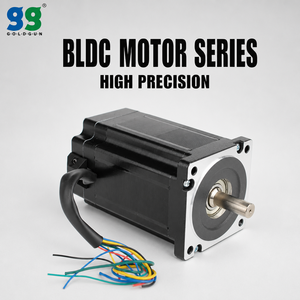
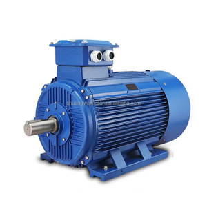
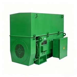
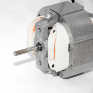
Explore our core range of low-voltage, medium-voltage, and custom direct-current horizontal foot-mounted electric motors manufactured for rigorous continuous duty (S1) across global processing plants.
In heavy industrial processing, the mechanical mounting configuration of an electric motor directly determines mechanical stability, torsional vibration damping, bearing lifespan, and long-term drivetrain alignment. As a primary global manufacturer and OEM supplier of horizontal foot mounted motors, our engineering designs adhere rigorously to International Electrotechnical Commission standard IEC 60034-7 (Code I: IM B3; Code II: IM 1001).
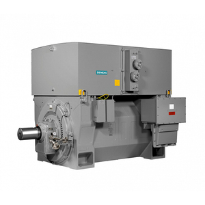
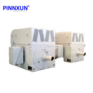
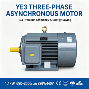
Foot-mounted construction features integrally cast or heavily welded rigid structural feet positioned at the base of the stator housing. These mounting feet are precision-machined to establish an exact center-height tolerance (Dimension H) relative to the shaft centerline. When bolting down to heavy steel baseplates or concrete foundations, horizontal foot-mounted motors absorb extreme dynamic radial forces generated by heavy mechanical loads such as industrial crushers, centrifugal pumps, boiler fans, and rolling mill gearboxes.
Unlike light-duty aluminum motors that suffer from thermal warping and frame distortion under cyclic stress, premium industrial horizontal foot-mounted motors are manufactured with high-tensile GG25 to GGG40 gray cast iron or heavy structural plate steel. The foot design incorporates reinforced gussets and anti-vibration web ribs that evenly distribute mechanical stress across four primary anchor points.
Critical mechanical metrics in our foot-mounted motor engineering include:
Selecting the correct motor mounting and cooling topology requires balancing mechanical load orientation against ambient environmental hazards. The table below outlines key technical differences across common industrial motor designs.
| Mounting Standard (IEC 60034-7) | Mechanical Structure | Primary Load Orientation | Cooling Method (IEC 60034-6) | Ideal Heavy Industrial Applications |
|---|---|---|---|---|
| IM B3 (IM 1001) | Horizontal Foot Mounted (Feet on Bottom, Shaft Horizontal) | High Radial & Torsional Loads; Heavy Direct Coupling | IC 411 (Self-Ventilated TEFC) / IC 611 (Air-Air Heat Exchanger) | Boiler Feed Pumps, Heavy Compressors, Ball Mills, Conveyors, Mining Fans |
| IM B5 (IM 3001) | Horizontal Flange Mounted (No Feet, Drive-End Flange) | Axial Alignment Loads; Direct Gearbox Mounting | IC 411 (TEFC) / IC 416 (Forced External Blower) | Direct Drive Gear Reducers, In-line Hydraulic Pumps, Agitators |
| IM B35 (IM 2001) | Combination Foot & Flange Mounted | Dual Radial Support + Precision Axial Flange Alignment | IC 81W (Air-to-Water Cooling) / IC 411 | Heavy Ship Thrusters, Rolling Mill Stand Drives, Extruders |
| IM V1 (IM 3011) | Vertical Flange Mounted (Shaft Downward) | High Axial Thrust Forces (Downward/Upward Thrust) | IC 01 (Open Drip Proof) / IC 81W (Water Cooled) | Vertical Deep-Well Turbine Pumps, Sewage Lift Stations, Pulverizers |
Built upon nearly a century of continuous electrical motor innovation in Germany, our custom horizontal motors deliver substantial operational advantages over standard commodity products.
Our medium and high-voltage stator coils undergo full-immersion VPI processing using Class H synthetic resin. This eliminates air voids, solidifies the winding mass against electromagnetic vibration, and prevents moisture ingress in harsh ambient conditions (marine O&G, wet paper mills).
To eliminate bearing fluting caused by Variable Frequency Drive (VFD) capacitive shaft currents, our motors incorporate ceramic insulated non-drive end bearings (SKF/FAG) alongside grounding rings, guaranteeing L10h bearing life ratings exceeding 100,000 continuous hours.
Equipped with dual internal/external cooling fans, optimized cast-iron cooling ribs (IC 411) or top-mounted air-to-air (IC 611) and air-to-water (IC 81W) heat exchangers, ensuring winding temperature rises remain well below Class B limits despite Class F/H insulation ratings.
The global heavy industrial sector is undergoing a massive transformation driven by carbon reduction mandates, predictive maintenance compliance, and total lifecycle energy economics. Procurement teams and engineering directors must account for five pivotal market trends when specifying foot-mounted motors:
With electricity accounting for over 92% of an industrial motor's total cost of ownership (TCO) over a 20-year lifespan, procurement strategy has shifted from initial purchase price to efficiency optimization. Modern foot-mounted squirrel cage motors are increasingly mandated to meet IE4 Super-Premium Efficiency standards under IEC 60034-30-1, significantly lowering megawatt-hour consumption.
Unplanned downtime in cement plants or oil refineries can cost upwards of $50,000 per hour. Modern horizontal foot-mounted motors are now supplied pre-fitted with tri-axial wireless vibration sensors (ISO 10816 compliant) and embedded dual PT100 resistance temperature detectors in winding slots and bearing housings for real-time cloud analytics.
As aging industrial facilities modernise infrastructure built in the mid-to-late 20th century, replacing legacy foot-mounted motors with identical footprint dimensions is essential. Leading manufacturers now provide custom foot-adaptor plates, modified shaft extensions, and matching terminal box placements to drop new motors onto existing foundations without civil concrete alterations.
The widespread adoption of high-power medium-voltage variable frequency drives requires stator insulation capable of withstanding repetitive peak voltage spikes (dv/dt) exceeding 12 kV/μs. Advanced horizontal motors utilize corona-resistant magnet wire and phase insulation reinforced against inverter-induced surge wave stress.
When issuing a Request for Quotation (RFQ) or procuring heavy-duty horizontal foot-mounted motors for industrial plant integration, evaluate vendor proposals against this 4-step engineering verification protocol:
Verify frame size (IEC 80–900), foot bolt hole centers (A, B dimensions), shaft diameter (D), shaft length (E), center height (H), and radial force capacity against driven equipment specs.
Define operating duty cycle (S1 continuous to S9 drive-integrated), voltage supply variations (±10%), starting torque ratio (Locked Rotor Torque Tl/Tn), and efficiency rating (IE3/IE4).
Select enclosure protection (IP55 dust-protected, IP65/IP66 washdown, or ATEX Ex p / Ex ec for explosive hazardous atmospheres) and ambient thermal limits (-40°C to +60°C).
Insist on factory acceptance testing (FAT) conducted in a dedicated full-load test bay, including vibration spectrum analysis, thermal rise test curves, and insulation surge testing.
Since 1927, MENZEL has stood as a world-renowned German manufacturer and fast-track global supplier of heavy industrial electric motors. Specializing in customized AC and DC motor solutions up to 25 MW and 13.8 kV, our company bridges the gap between standard off-the-shelf motors and complex custom-engineered drive systems.
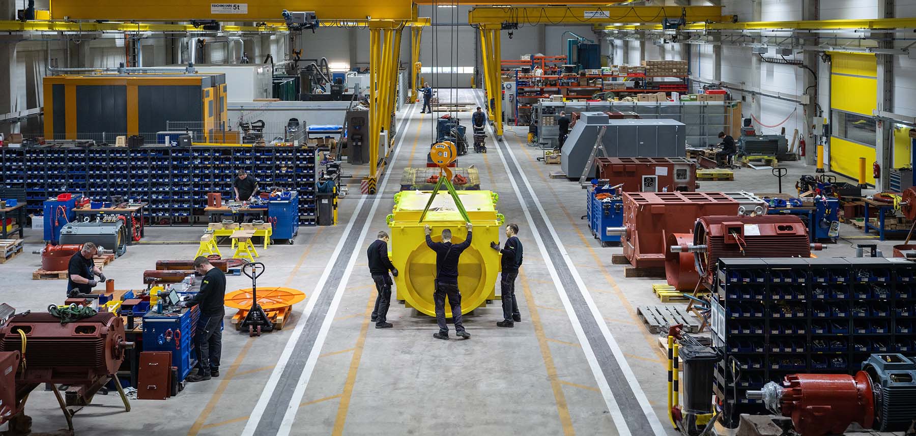
Unlike simple stocking distributors, MENZEL operates complete state-of-the-art manufacturing facilities in Germany. Our production infrastructure includes heavy mechanical machining, automated coil winding, VPI insulation plants, metal fabrication shops, and an advanced multi-megawatt load test field.
Global plant operators choose MENZEL for emergency motor replacement because we maintain one of Europe's largest immediate stocks of high-voltage and low-voltage horizontal foot-mounted motors, allowing dispatch within 24 to 48 hours for plant standstill emergencies.
Find authoritative technical answers to common queries raised by procurement teams, maintenance engineers, and plant operators.
IM B3 (IM 1001) refers strictly to foot-mounted horizontal motors attached to a base frame. IM B5 (IM 3001) is flange-mounted with no feet. IM B35 (IM 2001) combines both foot pads and drive-end flange mounting, allowing dual support for extreme radial and axial stability.
Soft foot occurs when one of the four mounting feet does not rest flush on the baseplate. It must be diagnosed using precision dial indicators or laser alignment tools and corrected using stainless steel shims before tightening mounting bolts, preventing frame twisting and bearing failure.
Operating a standard B3 foot-mounted motor vertically (shaft down or up) requires engineering approval. The bearing assembly must be rated for vertical axial thrust loads, and rain canopy/drip covers must be added to preserve enclosure IP protection ratings.
Cast iron (GG25/GGG40) provides superior structural stiffness, corrosion resistance, and vibration damping, making it ideal for heavy processing plants. Fabricated steel frames are utilized for ultra-large medium-voltage motors (above 2,000 kW) for flexible custom dimensions.
For direct coupling, standard deep-groove ball bearings are used. However, for belt-driven applications exerting high radial forces, heavy-duty cylindrical roller bearings (e.g., NU series) are fitted on the drive end to prevent shaft deflection.
IC 411 (rib-cooled TEFC) is standard up to 1,000 kW. Above this power, IC 611 (air-to-air heat exchanger mounted on top of the stator) or IC 81W (air-to-water cooling jacket) are standard for efficient heat dissipation.
Yes, provided the motor winding features inverter-duty magnet wire, Class H VPI insulation, and insulated NDE bearings (or shaft grounding rings) to protect against shaft voltages induced by high-frequency PWM switching.
Thanks to Europe's largest stock of large industrial AC and DC motors, standard or pre-adapted horizontal foot-mounted replacement motors up to 15,000 kW can be modified, tested, and dispatched within 24 to 48 hours.
Our senior electrical engineers are ready to evaluate your drive requirements, select exact foot mounting dimensions, and provide competitive B2B factory pricing.