1. Executive Summary & Industrial VFD Motor Engineering Landscape
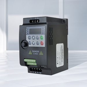
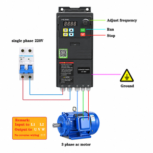
Modern industrial automation relies heavily on Variable Frequency Drives (VFDs)—also known as Variable Speed Drives (VSDs) or AC frequency converters—to regulate rotational speed, optimize process control, and achieve unprecedented energy savings. However, pairing a standard fixed-speed AC induction motor with a pulse-width modulated (PWM) inverter can lead to catastrophic electrical and mechanical failures. High-speed switching transistors (such as Insulated Gate Bipolar Transistors or IGBTs) produce extremely rapid voltage rise times (high dV/dt), microsecond peak voltage spikes, severe electrical discharge machining (EDM) shaft currents, and intense harmonic heating.
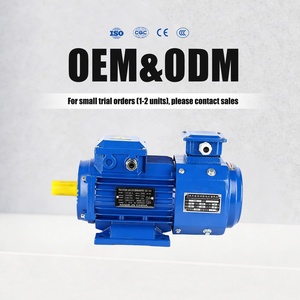
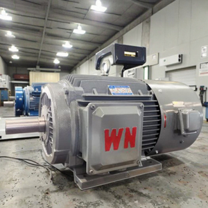
To withstand these extreme operating stresses, Tier-1 Chinese manufacturers have pioneered advanced Inverter-Duty VFD Motors and Permanent Magnet Synchronous Motors (PMSMs) engineered specifically for continuous variable-speed operation. As a senior industrial motor OEM, our engineering framework integrates Class H corona-resistant magnet wire, dual-layer Vacuum Pressure Impregnation (VPI), insulated bearings, conductive shaft grounding rings, and independent forced cooling units (IC416). This white paper offers industrial plant managers, procurement teams, and system integrators a comprehensive technical evaluation of China's top VFD motor manufacturing standards, custom selection frameworks, future technology trends, and global sourcing strategies.
dV/dt & Corona Resistance
Specially formulated Class H spike-resistant magnet wire designed to handle $dV/dt$ voltage rise rates exceeding 10,000 V/µs and surge voltages up to 2,200V without dielectric breakdown.
Bearing Protection & EDM Mitigation
Equipped with insulated ceramic/hybrid bearings at the non-drive end (NDE) and micro-fiber shaft grounding rings at the drive end (DE) to safely divert capacitive bearing currents.
IC416 Forced Ventilation
Auxiliary constant-speed blower fans ensuring full rated thermal dissipation even during low-speed continuous constant-torque operation (down to 0 Hz / standstill).
Information Gain: Why Standard Motors Fail Under VFD Power
When powered directly by sinusoidal mains (50/60Hz grid), an AC motor experiences smooth voltage waveforms. Under VFD control, the motor receives thousands of high-frequency rectangular voltage pulses per second (PWM switching frequencies between 2kHz and 16kHz). This creates steep voltage wave reflections across supply cables exceeding 20 meters, effectively doubling peak terminal voltages and generating aggressive Partial Discharge (PD) inside stator insulation slots, quickly burning out standard motors.
2. Technical Comparison Matrix: Standard Motors vs. Inverter-Duty VFD Motors vs. Permanent Magnet Synchronous Motors (PMSM)
Selecting the optimal motor topography requires balancing energy efficiency, initial capital expenditure, constant torque speed range, and harsh environment endurance. The matrix below outlines key engineering performance indicators across primary industrial drive categories:
3. Engineering Deep-Dive: Insulation Systems, Thermal Dynamics & Shaft Currents
Achieving a 20- to 30-year operational life under severe inverter duty demands rigorous mechanical and electrical engineering at the OEM factory level. China's top VFD motor manufacturing facilities adhere strictly to IEC 60034-18-41 and NEMA MG1 Part 31 standards. Below is an engineering breakdown of critical design components:
3.1 Vacuum Pressure Impregnation (VPI) Class H Insulation
Standard dip-and-bake varnish methods leave microscopic air voids within stator slot windings. Under high switching frequency pulses, air gaps experience localized ionization, triggering continuous partial discharge that degrades enamel wire. Advanced Chinese factories utilize automated Vacuum Pressure Impregnation (VPI) systems with 100% solventless epoxy resins. The stator core is evacuated down to <1 mbar vacuum before high-pressure resin injection (up to 6 bar), completely filling all inter-turn gaps, enhancing dielectric strength, thermal conductivity, and mechanical rigidity against electromagnetic vibration forces.
3.2 Bearing Protection & Common-Mode Voltage (CMV) Mitigation
High-frequency PWM inverters induce a parasitic capacitive coupling voltage between stator windings and the rotor shaft. When shaft voltage exceeds the dielectric breakdown threshold of the bearing lubricant film (typically 10V–30V), sudden micro-arcing occurs, creating microscopic cratering (fluting) on bearing race tracks. To eliminate EDM failures:
- Non-Drive End (NDE) Insulation: High-tensile alumina ($Al_2O_3$) plasma-sprayed ceramic coating applied to bearing journals or insulated inner/outer rings interrupts the electrical loop.
- Drive End (DE) Shaft Grounding: Silver-alloy micro-fiber conductive shaft grounding brushes or AEGIS rings maintain continuous contact with the shaft, bleeding off capacitive voltage safely to frame ground.
3.3 Thermal Derating & Cooling Topographies (IC411 vs. IC416)
An AC induction motor's internal cooling fan speed drops linearly with operating frequency. In variable torque applications (such as centrifugal water pumps or HVAC fans), load torque decreases quadratically with speed ($T \propto N^2$), making standard IC411 self-cooling sufficient. However, for constant torque applications (mining conveyors, extruders, positive displacement pumps, cranes, and shredders), the motor delivers 100% full load torque at low frequencies (e.g., 5Hz to 15Hz). Without an independent constant-speed blower fan (IC416 cooling), motor temperatures rapidly exceed allowable Class F/H limits, destroying winding insulation.
Procurement Pro-Tip: Sizing Inverter-Duty Motors for Extreme Speeds
When operating motors above base frequency (field weakening regime, e.g., 50Hz to 120Hz), mechanical balance becomes paramount. China's top OEM manufacturers dynamically balance rotors according to ISO 1940-1 Grade G1.0 and install high-speed precision bearings with specialized synthetic grease (such as Mobil Polyrex EM) to handle centrifugal stresses and elevated operating frequencies.
4. Future Procurement Trends & Technology Roadmap (2025–2030)
The global electric motor industry is undergoing a massive shift driven by decarbonization mandates, energy efficiency regulations (EU MEPS, China GB18613-2020), and smart factory digitization. Procurement professionals sourcing VFD motors from China must align their sourcing strategies with the following technology trends:
Trend 1: Rapid Adoption of IE5 Permanent Magnet Synchronous Motors (PMSM)
Traditional asynchronous induction motors inherently suffer from rotor $I^2R$ copper losses. Permanent Magnet Synchronous Motors (such as the Wannan Electric TYCP Series featured in our product lineup) utilize high-coercivity Neodymium-Iron-Boron (NdFeB) permanent magnets within the rotor structure. By eliminating rotor excitation current, PMSMs achieve IE5 Ultra-Premium efficiency levels, reduce motor frame sizes by up to 2 frame numbers, and maintain high efficiency even at 25% partial load conditions.
Trend 2: Wide Bandgap (SiC & GaN) Inverter Integration
Next-generation VFD inverters feature Silicon Carbide (SiC) and Gallium Nitride (GaN) semiconductors capable of switching frequencies up to 50kHz with minimal switching loss. While improving inverter efficiency, SiC inverters produce ultra-steep voltage rise times ($dV/dt > 20,000 \text{ V/µs}$). Premium Chinese OEM motor manufacturers are developing specialized "Extreme Surge-Tough" insulation barriers utilizing polyimide film and nano-composite inter-phase insulation to seamlessly pair with SiC drives.
Trend 3: Smart Telemetry & Integrated Sensor Hubs
Industry 4.0 demands real-time health monitoring. Modern Chinese VFD motors are increasingly supplied with embedded PT100/PT1000 RTD thermal sensors in stator windings and bearing housings, tri-axial MEMS vibration sensors, and digital encoders (TTL/HTL/Absolute Encoders). These sensors transmit telemetry directly to cloud-based predictive maintenance systems, predicting bearing wear and insulation degradation long before operational downtime occurs.
Trend 4: Direct-Drive Gearless Motors
In heavy industrial applications like ball mills, cooling tower fans, and low-speed mixers, high-torque direct-drive PMSM motors are replacing traditional high-speed motors paired with mechanical gearboxes. By removing gearboxes, plants eliminate oil leaks, gearbox mechanical loss (3% to 7%), and routine gear maintenance, achieving direct mechanical coupling with supreme control accuracy.
5. Manufacturer Capabilities & Precision Manufacturing Workflow
Our featured manufacturing partners combine nearly a century of industrial legacy (retaining high-voltage engineering principles similar to European leaders like Menzel Elektromotoren) with China's world-class supply chain scale. Key manufacturing strengths include:
- In-House Manufacturing Depth: Complete vertical integration including high-speed stator lamination punching, CNC precision shaft turning, automatic copper wire coil winding, VPI impregnation tanks, and automated robotic paint booths.
- Comprehensive Testing Facilities: State-of-the-art full load test fields capable of testing motors up to 25,000 kW (25 MW) and voltage levels up to 13.8 kV under actual load conditions, including temperature rise tests, partial discharge (PD) verification, sound level analysis, and vibration spectrum testing.
- Custom Mechanical Adaptation: Custom shaft extensions (tapered, double-extension, splined), specialized mounting flanges (IEC B3, B5, B35, NEMA C-face, D-flange), heavy-duty cast iron frames (FC200/FC300), and custom IP65/IP66/IP67 weather-proof or explosion-proof enclosures (ATEX / IECEx certified).
6. Frequently Asked Questions (FAQ) for B2B Buyers
What is the main difference between an Inverter-Duty motor and a standard motor?
An inverter-duty motor features Class H corona-resistant insulation wire, dual VPI resin treatment, insulated non-drive bearings (to stop shaft currents), and often an independent cooling fan (IC416). Standard motors lack these protections and rapidly suffer insulation puncture and bearing fluting under VFD pulse-width modulation (PWM).
When is an IC416 forced cooling fan required over an IC411 self-cooling fan?
An IC416 independent blower fan is required when the motor operates continuously at low speeds (below 50% rated frequency) under constant torque loads (e.g., conveyors, positive displacement pumps, extruders). At low speeds, shaft-mounted IC411 fans cannot move enough air to dissipate motor heat.
How do long motor cables affect VFD motor insulation?
Long cable runs (typically over 20 meters / 65 feet) cause impedance mismatch wave reflections. Voltage pulses from the VFD reflect back, stacking onto incoming pulses and creating voltage peaks up to twice the DC bus voltage ($2 \times V_{dc} \approx 1400\text{V} - 1700\text{V}$). VFD motors feature peak surge insulation to withstand these reflections.
Why choose a Permanent Magnet Synchronous Motor (PMSM) over an induction motor?
PMSMs offer IE5 ultra-premium efficiency, saving 10% to 25% electrical energy compared to standard induction motors. They maintain high efficiency at partial loads, feature compact frame sizes, deliver superior dynamic response, and provide high continuous torque at low speeds.
What certifications are available for international export?
All Chinese OEM VFD motors comply with IEC/EN 60034 standards. Products can be certified with CE, UL, CSA, ISO9001, ISO14001, and ATEX/IECEx (for hazardous dust/gas environments Zone 1, Zone 2, Zone 21, Zone 22).
Can Chinese OEM manufacturers match custom foot-to-shaft dimensions of old motors?
Yes. Custom mechanical engineering is a key OEM strength. Factory engineers can match non-standard foot hole centers, shaft heights, shaft diameters, keyway dimensions, and terminal box positions to create a direct drop-in replacement for legacy European or American motors.
How do shaft grounding rings protect motor bearings?
Shaft grounding rings utilize conductive micro-fibers that ride on the motor shaft, providing a micro-ohm electrical pathway directly to frame ground. This prevents capacitive voltage from accumulating on the rotor shaft and arcing through bearing grease film.
What lead times can be expected for custom industrial VFD motors?
Standard frame motors (up to 315kW) in stock ship within 3 to 7 days. Customized low-voltage and high-voltage industrial VFD motors (up to 25MW) typically require 4 to 6 weeks for precision manufacturing, testing, and acceptance inspection.
7. Strategic B2B Sourcing Checklist for Engineering Buyers
To streamline technical inquiries and fast-track quotation requests, procurement engineers should prepare the following key parameters when contacting our OEM technical team:
- Driven Equipment & Load Type: Variable torque (centrifugal pump/fan) or Constant torque (conveyor, mixer, extruder, hoist).
- Power Rating & Speed Range: Rated output power (kW/HP), base synchronous speed (RPM), and minimum/maximum continuous operating speed.
- Inverter Power Supply Details: Supply voltage (220V, 380V, 460V, 690V, 3kV, 6.6kV, 10kV), VFD switching frequency (kHz), and cable distance between VFD and motor.
- Environmental Conditions: Ambient temperature range (-20°C to +60°C), altitude (>1000m derating), hazardous area rating (Ex d, Ex ec, Ex p), and IP enclosure protection rating (IP55, IP65, IP66).
- Feedback & Accessories: Encoder requirements (Incremental/Absolute), space heaters, winding PT100 RTDs, bearing temperature monitoring, and forced cooling fan voltage.